
I finished up the wireless servo actuated air pressure gauge. The last things remaining were to finish the transmitter, and make a small transmitter box to house the transmitter PCB with a dial and markings corresponding to the servo actuated gauge.
To summarize Part 1 of the servo actuated gauge project:
I fixed up a mini servo and installed it in the gauge with a four-bar-linkage. I also ordered a Hobby King GT-2 2.4Ghz 2Ch Tx & Rx (the same one I used for the Electric Orbit Wheels) to control the servo from a distance. After it came in, I could start working with the transmitter end.

The Hobby King controller comes with a handy little binding device to connect the servo and ground on channel three of the receiver. I moved one of the leads to the center to make a battery plug.

The receiver calls for between 5V and 6V. So I quickly made a voltage divider with a 24 kΩ and a 15 kΩ resistor to get an output voltage of 5.5V (I got the resistors from the Edgerton Center Rm. 4-409).


Testing the voltage divider.
I think the 5.5V voltage divider interferes with the transmitter and receiver binding. Because I don't get the same ghost issues when I use 6V from the 12V pack. I ended up scrapping the voltage divider and using the full 9V. It seemed to handle it fine.

I didn't want to use the Hobby King controller for the final controller, so I used an old plastic soap container.

The transmitter PCB and batteries barely fit.
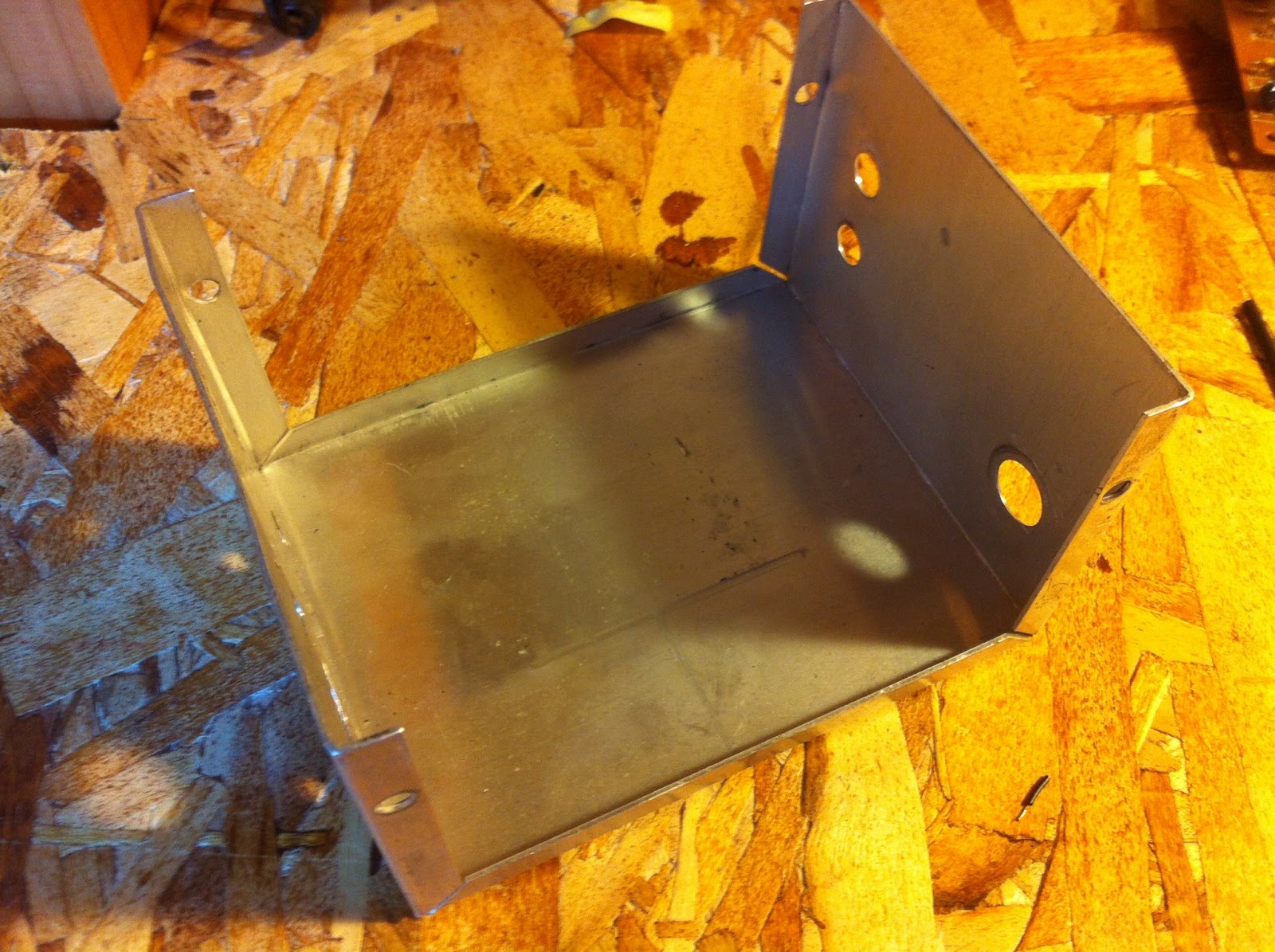
I changed my mind about the soap container. It looks a little to sketchy and I wanted to hide all the electronics. Rather than having the transparent plastic, I took apart a former transformer's metal housing. This will also allow me to use the 12V AA battery pack which might help with some of the ghost binding problems.
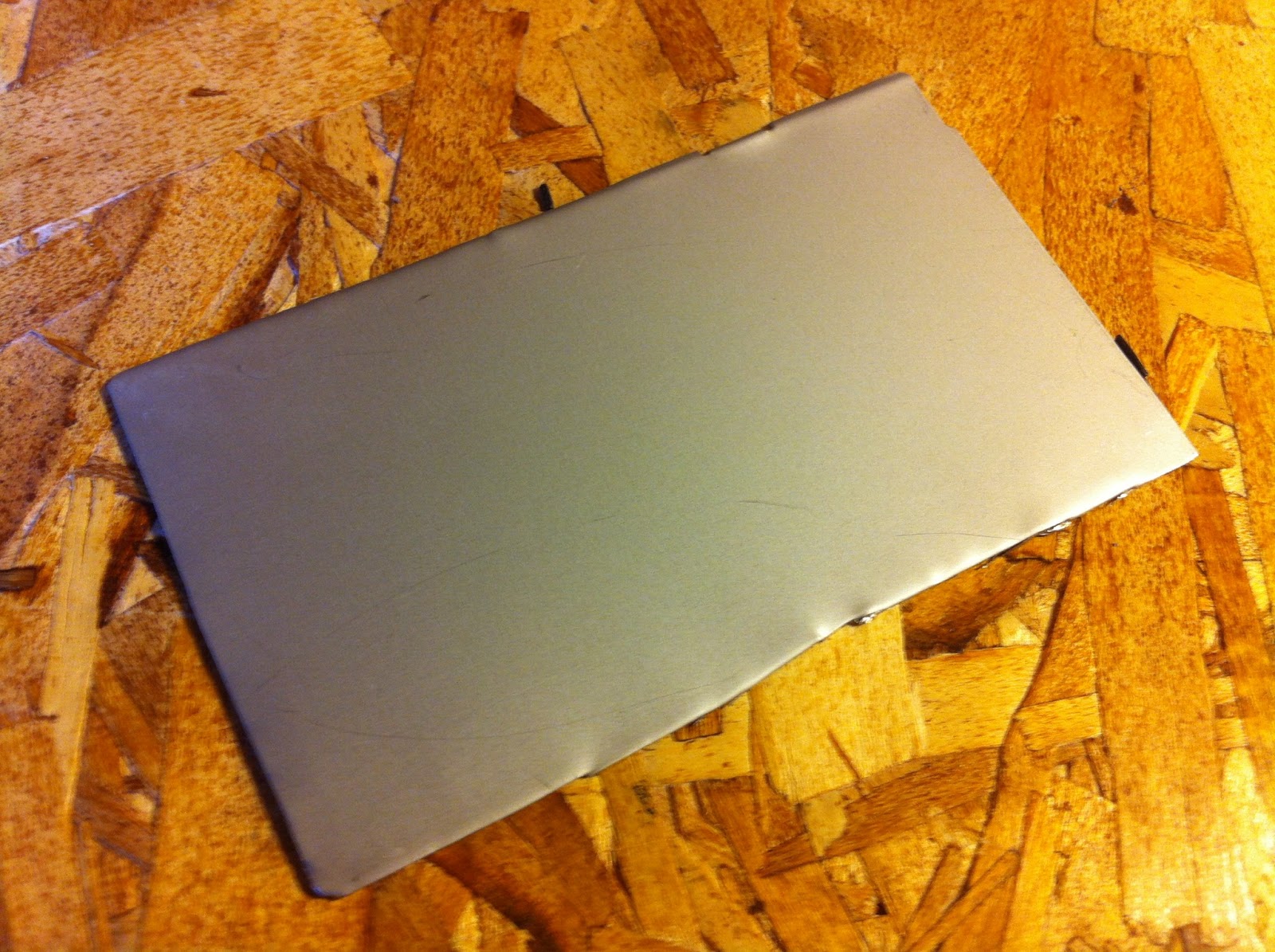
I crufted a bunch of power supplies seeking for 250wv 330uF capacitors for a broken 42" LG TV. So I cut up some of their covers to make sides for the transformer box.

My Dad always used to say, "Keep your work space clean". Hmmm...

One problem with having a metal container rather than a plastic container... things short! I taped up parts that might come in contact with the metal box.

I hot glued a piece of acrylic I had lying around to the bottom of the transmitter PCB. Funny thing about hot gluing acrylic, it warps and bends from the heat.

I then glued all the transmitter components inside the metal transformer box.

Here's a picture of the transmitter box and receiver. I figured out some of the binding issues with the receiver and transmitter. I had previously thought that switching between the same potentiometers from identical remote controllers wouldn't change anything. However, it was interfering with the binding between transmitter and receiver. It turned out that the potentiometer had to be centered because on the remote controller there were springs that would ensure the potentiometers ended up with the center specific resistance. The same thing would happen if you were to pull the trigger and try to bind the transmitter and receiver (which seems very odd to do with the device when its all professionally packaged up, but easy to go unnoticed when hacked).

I stuffed the RC receiver in the hacked air pressure gauge and cut out a space in the cover for the servo. Rather than adding a switch, I just glued the 9V on the outside so the clip can be easily removed.

Control box with knob and corresponding needle values labeled.
Because the gauge used to be an air pressure gauge, it was geared for torque inside. This allowed for the small flex in metal tubing (when air pressure was applied) to have a greater affect on the needle. However, in this case it makes the system very sensitive. I can turn the needle 300 degrees with only turning the control potentiometer 20 degrees.
It works. Though, I may change the sensitivity later on.
[]
No comments:
Post a Comment