

The ring gear was the main reason I decided to make my own wheel. I couldn't find any wheels without hubs that also had a ring gear inside. So I designed a wheel rim with a bunch of water jetted aluminum rings (one being the ring gear). The ring gear was the most stubborn of the bunch. It really tested my dedication to this project. There were a few times that I ran out of ideas on how to make it. But I persisted. I was probably doing it completely wrong, but I came up with a solution that worked using Autodesk's gear generator.
First, I designed the ring which the bearings will ride on (ring bearing track) and the ridges that will keep the bearings on the bearing track (track ridges).

The elongated holes allow for the urethane to seep in and interlock with the aluminum rim. The inner diameter is 7" and the outer is 7.8" to give 0.4" for the holes and to fit in the 8" wide aluminum stock I purchased from McMaster.

The track ridge parts have an 6.8" inner diameter to provide a 0.1" ridge for the bearings. I decided to make this part a third of a full circle, because it will reduce the amount of aluminum waste. I can pack them tightly together in Omax Layout for the water jet.

I made the water jet path come completely away from the part between each cut (shown by the green "shark teeth"). Therefore, we could check on the part if something wasn't cutting properly.
Now for the ring gear.

I used the Autodesk gear generator (in the assembly mode). I ended up spending a whole day playing with these numbers. After awhile, I built an intuition for what the numbers will change on the gear.
I searched for spur gears on the SDP-SI (Stock Drive Products/Sterling Instruments) website. (They have an amazing selection of mechanical parts (comparable to McMaster)). I decided to find a spur gear, and then design the ring gear around it to give myself some constraints. This gave me some values I needed in the Autodesk gear generator (like the pitch diameter and such). I found a 16 tooth gear with a 24 ul/in. pitch diameter.
SDP-SI, being the awesome online mechanical parts store they are, had a CAD file for each of their gears. I imported it into Autodesk and then "eye-balled" its fit with the ring gear.

I mostly tweaked the gear ratio and center distance to get the ring gear to fit with the spur gear from SDP-SI and my CADed rim (ending up with a 10.375 gear ratio. (166 teeth on the ring gear, 16 teeth on the spur gear)). To get the teeth and holes, I took the ring bearing track and selected the inside surface for the feature in the gear generator.

Success!
Here's the finished rim assembly.

In between CADing the wheel assembly and ring gear, I CADed up a mold to be 3D printed on the IDC's 3D printer.

The little pegs sticking out the side of the top mold will friction fit into the bottom mold piece.

I put a small fillet in on the corner to make the urethane wheel rounded on the edges (but still flat in the middle).
Printed.

I laser cut a prototype ring gear to make sure it fit in the 3D printed mold and matched the teeth on the 16 tooth spur gear before I committed to water jetting it.

I designed a two part mold to help with taking the wheel out after the urethane has been poured.

The little pieces that look like small top hats are inserts into the main mold frame to suspend the wheel rim in the mold. This will enable the urethane to have the same thickness on both sides of the rim.

This time I had enough experience to be able to operate it. I would like to give a huge thanks to Kyle for helping me with all the water jetting and for his patience during the process.

I was able to combine parts in OMAX layout to get the most out of my aluminum sheet. Here's a photo of the printed bottom plate and the ring bearing track.
I set the ring gear on the highest quality (quality 5) to make sure the teeth came out perfect and would mesh with the spur gear. (I also didn't change the tool offset, because the ring gear needed to be the exact dimensions as they were in the CAD file).


The bearings I'm using have dimensions: 8 mm Inner Diameter, 22 mm Outer Diameter, and 7 mm Width. 7 mm is about 0.275 inches which is slightly wider than 1/4" aluminum. I used sheet metal with 1/16" thickness to shim between the bearing guides (ridges) to make a track 0.3125" wide.

The bearings fit in the track with very little slop.

Now for putting the entire wheel assembly together. I countersunk the six track ridge pieces that will be on the outside of the wheel.

I alternated the track ridges so the meeting point of two thirds was the center of one third on the second layer (staggering the pieces). I then threaded the middle three holes, and drilled through. I also carefully planned the hole diameters for the ring gear and two bearing track rings (because I didn't want to have to water jet them a second time, plus I didn't have enough material to do so).

Comparison to the CAD assembly:

Once I got all the proper holes drilled 0.173" and the 0.144" holes tapped, I screwed them together with 1 1/4" 8-32 screws alternating in pairs of three. The screws are screwed in from both directions resulting with a screw in every hole. I did it this way to get rid of nuts. It also makes both sides of the wheel flat to prevent big gaps between the front and back plates.
Now for the spacers to hold the bearings in their respective tracks. The spacers will also keep the wheel from rubbing on the sides of the front and back plates.

I found some aluminum rod stock 3/8" in diameter at MITERS. I put it on the lathe and bored out a 0.28" hole for the steel rods to fit in. Then I used the parting tool to make 15 spacers.

The aluminum spacers separate the bearings so they don't rub on the ridges in the wheel rim.
I put the ring gear on the side (rather than in the center of the wheel), because the motor shaft isn't long enough to support a spur gear in the center of the wheel. Now it reaches without a problem. I don't think it will matter too much that I won't have the bearing centered, because they will be leaning as I ride. It's also fairly robust as it is.
I didn't have to loosen the steel rods to put the bearings and wheel on. I managed to slid them on all at once.

I designed the bearing configuration similar to my commercial orbit wheels. The three double bearings on the bottom help support my weight, and the top three keep the orbit wheel secure (they will also help with bumping into curbs or walls to stop).

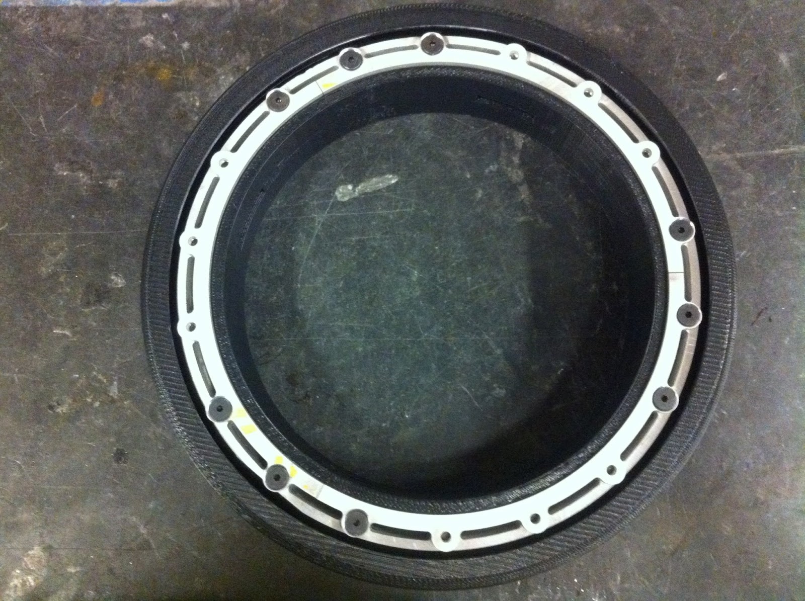
A rolling frame! The rim is finished and the bearings are in place. It looks like my CADed assembly. It is pretty much finished mechanically. Now all it needs is a motor, batteries, and electronics. Oh! and a...

Croc.

Thanks so much for posting this! It has really answered some of my questions about urethane parts... Thanks for all your help!
ReplyDeleteI think they provide the most quality of bearing and gears...
ReplyDeleteMRO Supply com.
Thank you for this I've been looking for urethane parts and this site has really helped me know what I really need.
ReplyDelete